Introduction Current Transformers (CTs) are used in power systems to measure current levels and provide accurate readings for various purposes, including billing, monitoring, and control. In addition, CTs are also used as protection transformers in protective applications, where they help to protect electrical infrastructure against overloading and short-circuits. In this blog, we will discuss how current transformer is used for protection.
In protective applications, CTs are sized differently than in normal measurement applications. This is primarily because the burden of the protective relay may be larger than that of the measuring instrument. As a result, CTs used in protective applications are generally larger in size to ensure that they can handle the higher burden. The core must also be large enough to avoid saturation when the CT experiences a high current on the primary. It is during this overcurrent that the CT must maintain its proportionality to ensure adequate protection.
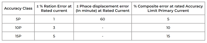
| Accuracy Class | ± % Ration Error at Rated current | ± Phace displacement error (In minute) at Rated Current | % Composite error at rated Accuracy Limit Primary Current |
|---|---|---|---|
| 5P | 1 | 60 | 5 |
| 10P | 3 | – | 10 |
| 15P | 5 | – | 15 |
why is knee point voltage important?
It is particularly crucial for protection CTs, which are designed for protective purposes. Protection CTs typically have a higher burden than metering class CTs, leading to a high voltage drop across the burden. As a result, the knee point voltage of a protection class CT must exceed the voltage drop across the burden to maintain the CT core within its linear zone.
How CTs are used in Protective Applications
In protective applications, the secondary leads of the CTs are connected to sensitive measuring equipment, known as protective relays. These relays trip a protective device (breaker) when the circuit sees an over-current, caused by overloading the circuit or typically caused by a short circuit. The CT supplies current magnitudes to the relays to carry out protection functions during a fault condition while permitting other parts of the plant to continue in operation.
During a fault condition, the current in the primary circuit will increase, causing a proportional increase in the current in the secondary circuit of the CT. The protective relay will sense this increase in current and send a signal to the protective device to trip, isolating the faulty part of the circuit. The CTs used in protective applications must be accurate, reliable, and able to handle high currents and overloads. They must also have a high ALF to ensure that they can accurately sense the fault current.
Conclusion: Current Transformers are used in power systems for various purposes, including measuring current levels and protecting electrical infrastructure against overloading and short-circuits. CTs used in protective applications must be sized and designed differently than those used in normal measurement applications.
© Copyrights Straton Electricals Pvt. Ltd. 2024 . All rights reserved. Designed and Maintained By IRDM