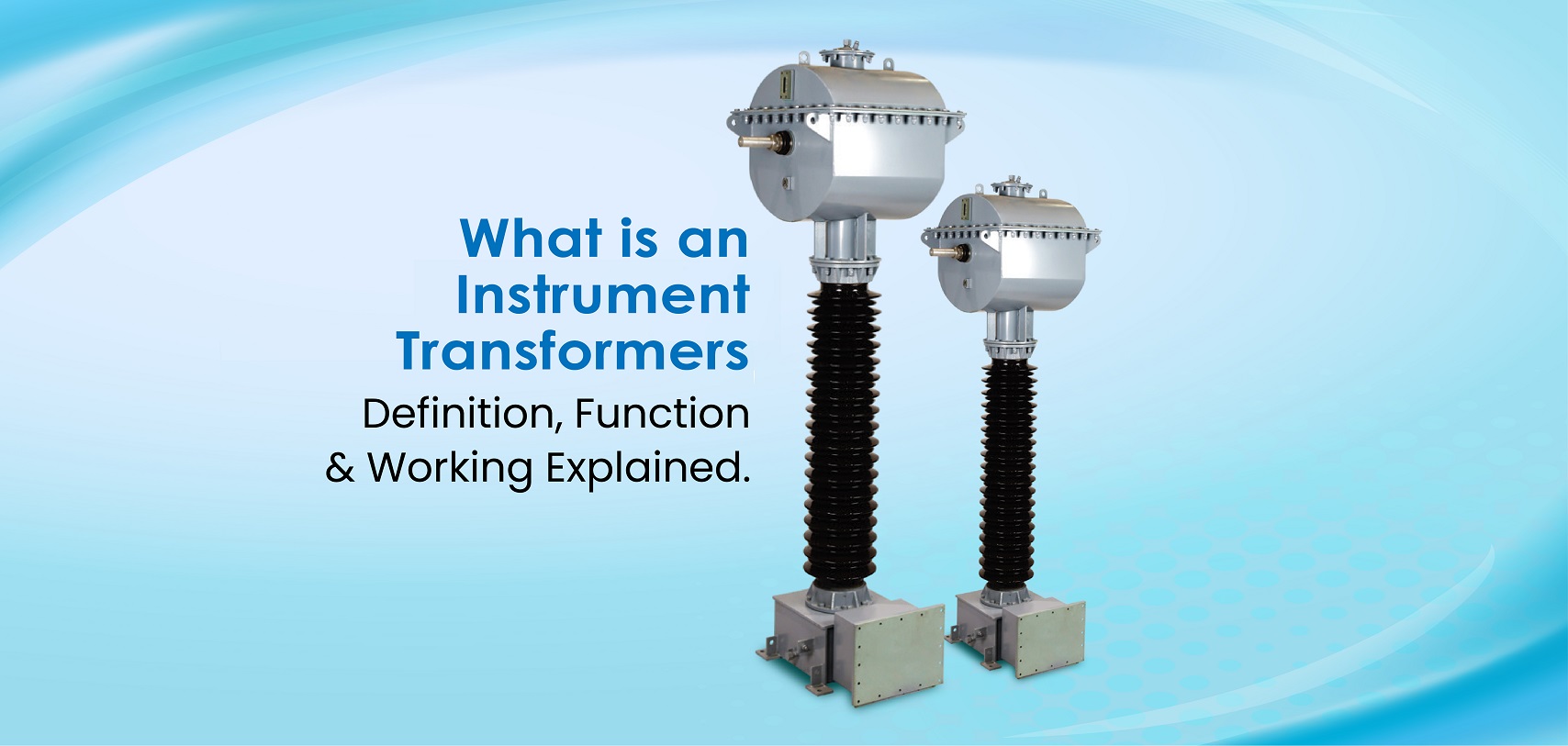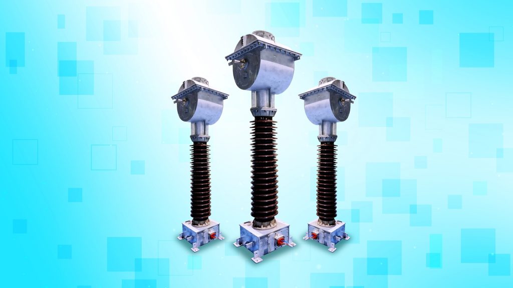
In modern power systems, an instrument transformer is the precision link between high-voltage networks acting as a measuring instrument. Its main function is to accurately transform current and voltage to standardized, measurable levels for metering and protective devices. Based on the principle of electromagnetic induction, the primary winding handles system voltage or current, while the secondary winding delivers a proportional, output. Precision-engineered insulation system build ensures electrical isolation without affecting accuracy. Whether used in substations or industrial setups, instrument transformers enable precise voltage and current measurement, the cornerstone of reliable monitoring, control, and system performance.
At Straton Electricals, we combine decades of transformer design expertise with advanced materials and testing protocols, manufacturing reliable CT and PT solutions from 3.3kV to 245kV that meet the evolving demands of smart grids, substation automation, and mission-critical power distribution systems.
Instrument transformers are broadly classified into Current Transformers (CTs) and Potential Transformers (PTs), each serving distinct roles in electrical systems.
| Current measurement | Principle | Typical use |
| Conventional current transformer (CT) | Electromagnetic transformer steps primary current down to a standardized secondary for metering and protection . | Substations and industrial switchgear for protection and metering inputs to relays and meters . |
| Low‑power current transformer/sensor (LPCT; LPIT family) | Sensors defined in IEC 61869‑6 to 10 provide low‑level analog/digital outputs compatible with IEDs and process bus . | GIS/AIS integration and digital substations where compact sensors and IEC 61850/61869 interfaces are used . |
| Rogowski coil | Air‑core coil produces a voltage proportional to di/dt; an integrator yields a signal proportional to current, making it ideal for AC and transients . | Wide‑band, high‑current or transient measurements where non‑saturating, flexible sensing is needed . |
| Optical CT (Faraday effect) | Magneto‑optic rotation of polarization is proportional to enclosed current per Faraday effect, enabling wide bandwidth and EMI immunity . | High‑voltage environments requiring galvanic isolation, wide dynamic range, and fiber transmission . |
| Voltage measurement | Principle | Typical use |
| Inductive VT/PT | Electromagnetic transformer steps down primary voltage by turns ratio for accurate metering and protection . | Substations and industrial systems for relay and meter voltage inputs with isolation . |
| Capacitive VT (CVT) | Capacitor voltage transformer reduces line voltage to an intermediate level, then an electromagnetic unit further steps it to standard secondary levels . | EHV transmission where CVTs provide cost‑effective VT functionality and coupling for power‑line carrier . |
| Resistive divider | High‑value resistor chain scales high voltage to a safe low‑voltage output for measurement . | DC and low‑frequency HV measurement and calibration with precision DVMs or references . |
| Capacitive divider | Series capacitors form a divider to scale high voltage, often used as the front end of CVTs or for high‑frequency signals . | HV measurement and as the divider stage in CVTs for EHV systems . |
| Compensated R‑divider | Frequency‑compensated resistive divider (R with parallel/series C network) keeps ratio flat over wider bandwidths . | Precision power/AC measurements over extended frequency ranges compared to pure resistive chains . |
| RC divider (Resistive‑Capacitive) | Combined resistive and capacitive elements yield wide bandwidth, ferroresonance‑free behavior, and DC–kHz operation for power‑quality monitoring . | AC/DC voltage measurement in HV networks, including harmonics and transient capture . |
| Optical VT (Pockels effect) | Electro‑optic birefringence in crystals (linear with electric field) modulates light polarization to sense voltage . | Optical voltage sensors with high isolation, wide bandwidth, and fiber links in HV environments . |
Understanding the CT PT difference is essential when designing or maintaining high-voltage systems. Both Current Transformers (CTs) and Potential Transformers (PTs) play vital roles in ensuring accurate current and voltage measurement in power networks.
Straton Electricals emphasizes on custom-built CT and PT products for diverse voltage classes. Their commitment to precision and scalability makes them a trusted partner for global energy infrastructure.
CT and PT units are known to be eyes and ears of modern power grids, feeding accurate data to protection systems and metering equipment. In substations, they work alongside circuit breakers and switchgear to detect faults and isolate problems before damage spreads. The importance shown daily in energy metering billing depends on their precision. Industrial automation relies heavily on these instrument transformers for process control and monitoring. Without CT tracking current flow and PT measuring voltage levels, your entire grid would operate blind. They’re not optional accessories; they’re essential components that keep electrical infrastructure safe, monitored, and functioning efficiently across distribution networks.
The benefits are clear when you look at real-world applications. These devices let technicians safely monitor deadly voltages in substations without risk. Switchgear panels depend on them for relay coordination and fault detection. Grid monitoring becomes practical because CT PT systems deliver standardized signals that work with any meter or analyser. Electrical energy metering across commercial buildings relies on their accuracy for fair billing. In industrial automation, they enable precise process control by feeding clean data to PLCs and SCADA systems. The advantages extend beyond safety: they’re cost-effective, require minimal maintenance, and provide isolation between high-power circuits and sensitive instruments throughout distribution networks.
Current Transformers (CTs) and Potential Transformers (PTs) are indispensable components in modern electrical infrastructure. From substations to smart grids, their role in measurement, protection, and control is foundational to safe and efficient power distribution.
Understanding CT and PT: Core Functions and Uses
Straton’s CT and PT products are engineered for global compliance with IEC and other international standards. These transformers are essential in:

Straton Electricals’ instrument transformers deliver safe operation and accurate measurement that meet global standards.
Instrument transformers remain vital for safe operation and reliable measurement across any power system. Crucial to power system protection, they function as the monitoring nerve centre of modern grids. Trusted manufacturers like Straton Electricals deliver quality units that meet industry standards, ensuring your infrastructure stays protected and monitored effectively for years of dependable service.
An instrument transformer is a device used in electrical measurement systems to safely scale down high voltage or current. Its working principle ensures safe measurement and monitoring through precise voltage and current step-down conversion.
Instrument transformers are classified into two main types: Current Transformers (CT) and Potential Transformers (PT). These measurement transformers help monitor high voltage and current safely in power systems.
A Current Transformer (CT) uses electromagnetic induction to produce and isolated, proportional reduced magnitude of the primary AC current at its secondary winding, enabling safe measurement and monitoring.
A Potential Transformer (PT) uses electromagnetic induction to produce and isolated, proportional reduced magnitude of the primary AC voltage at its secondary winding to ensure safe and accurate voltage measurement.
CT and PT are widely used in smart grids, switchgear, and industrial automation for accurate energy metering, fault detection, and reliable electrical protection across high-voltage systems.