



A current transformer protection class current transformer is designed to maintain accuracy during fault conditions — high current surges — unlike metering CTs, which are optimised for accuracy at normal load. Protection CTs are typically classified as 5P, 10P, or PS class as per IS 16227 / IEC 61869‑2.
Selecting the wrong current transformer protection class is one of the more common — and costly — mistakes in protection system design. A CT that saturates before a relay’s trip threshold is reached can leave a fault undetected, risking equipment damage across substations, switchgear, generators, and transmission lines. Getting this right depends on matching the CT’s accuracy limit factor (ALF), knee point voltage, and burden to the actual relay and fault-level requirements — not on picking a class in isolation. This guide walks through how protection classes differ, what each parameter means, and how to choose correctly for real-world protection schemes.
Both are formalised under IEC 61869‑2 and IS 16227, but the standards define separate parameter sets precisely because the two CT types are built to fail in opposite ways for opposite reasons.
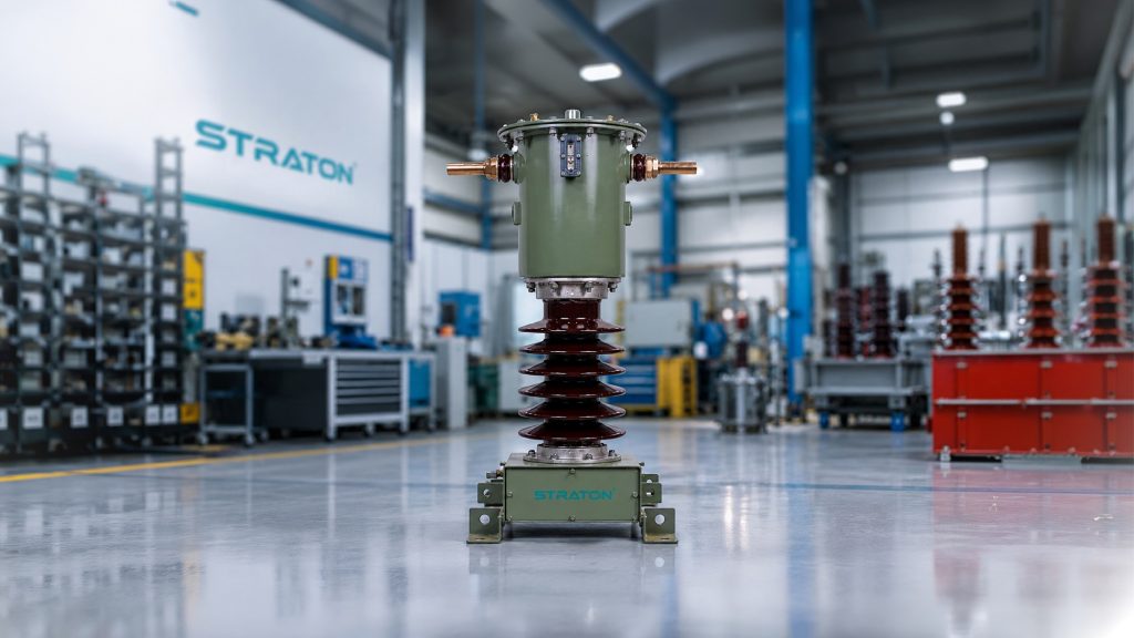
Protection current transformer (CT) for electrical fault protection and metering applications in an industrial transformer manufacturing facility.
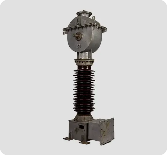 Wound |
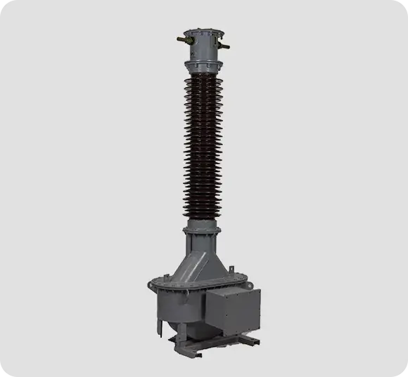 Eye Bolt |
 Rigid/Bar |
Most engineers do not search for current transformer CT out of curiosity. They search because they are writing a tender specification, responding to one, or checking that a supplier’s offer matches what was asked for. Getting a single field wrong in that specification can mean a CT that is manufactured correctly, delivered on time, and still unfit for the protection scheme it was bought for.
A complete instrument transformer specification is a compact string of parameters. Here is a representative example for a multi-core CT, of the kind used in a 132 kV substation feeder bay:
400–200 / 1–1–1 A, 3 cores Core 1: 15 VA, 0.2S, ISF < 5 (metering) Core 2: 15 VA, 5P20 (overcurrent / earth fault protection) Core 3: PS class, Vk ≥ 400 V, Imag ≤ 30 mA at Vk/2, Rct ≤ 5 Ω (busbar / differential protection)
Every element of that string carries meaning. Read field by field:
The primary current the CT is designed for. A dual-ratio primary — shown here as 400–200 A — allows the same CT to serve a feeder whose loading is expected to grow, with the ratio changed by primary reconnection or by tapped secondary windings. Specify the ratio against present and projected load, not present load alone; re-procuring a CT because the feeder was uprated is an avoidable cost.
This choice has consequences far beyond the number. Because burden rises with the square of secondary current, the same run of secondary cable imposes twenty-five times the burden on a 5 A CT that it does on a 1 A CT.
Where lead runs are long, a 1 A secondary is usually the correct engineering answer, and this decision should be made before the class and burden are fixed, because it changes both.
Metering and protection have opposite requirements. A metering core must saturate early to protect connected instruments during a fault; a protection core must stay linear far into the fault to keep the relay fed. One core cannot do both well. This is why a single instrument transformer carries separate cores on a common primary — one wound for metering accuracy, others wound for each protection function. A modern feeder bay commonly needs three; complex busbar and differential schemes can require more. Confirm the core count against every relay and meter in the bay before enquiry, because adding a core after manufacture is not possible.
The load, in volt-amperes, the CT will supply at rated secondary current while holding its stated class. It must cover relay burden + meter burden + secondary lead loop resistance + terminal blocks.
The most common specification error here is inherited over-specification: carrying forward a 30 VA figure from a legacy tender written for electromechanical relays, when modern numerical relays draw a fraction of a VA and the real burden is dominated by cable. Rated burden should be calculated for the circuit actually being built.
Under IEC 61869-2 / IS 16227, metering classes are 0.1, 0.2, 0.2S, 0.5, 0.5S and 1. The suffix S (“special”) denotes extended accuracy down to 1% of rated primary current — which is why class 0.2S is the standard demand for revenue and tariff metering, where a feeder may run lightly loaded for much of its life and every unit of energy is billed.
Note there is no class 0.3 in IEC or IS practice — Class 0.3 belongs to the American ANSI/IEEE C57.13 system and does not appear in Indian tender specifications.
The mirror image of ALF, and often omitted from specifications by mistake. ISF limits how far a metering core will reproduce current before it saturates. A low ISF (typically < 5 or < 10) means the metering core saturates early during a fault, protecting the connected energy meter from destructive current. A metering core specified without an ISF limit is a hazard to the instruments downstream.
Read as two parts:
The ALF must be chosen against the maximum fault current the relay must see and grade on — not against a habit. Under-sizing the ALF means the core saturates before the fault current peaks, the secondary current collapses, and the relay may under-reach or fail to trip.
For high-impedance busbar protection, restricted earth fault, and differential schemes, a fixed percentage-error class is not sufficient — these schemes depend on CTs on both sides of the protected zone behaving identically. The class is therefore specified by its magnetisation characteristic rather than by an error percentage:
A terminology note that trips up procurement: PX is the IEC 61869-2 designation, PS is the Indian (IS) designation, and Class X is the older British/legacy term. In practice these refer to the same family of knee-point-defined protection CTs. Indian tenders most often say PS.
Before an enquiry leaves your desk, confirm every one of the following:
Share the full circuit data — lead lengths, conductor cross-section, relay models, and the protection scheme — with your CT manufacturer at the enquiry stage. Correct specification before manufacture is far cheaper than a re-wound core afterwards.
Getting the current transformer protection class right often comes down to one number — the ALF — yet it’s the field most often under-sized in a tender spec.
| ALF Value | Fault Current Multiple | Recommended Application | Common Under-Sizing Mistake |
| 5 | 5× rated current | Low fault-level circuits, LV distribution feeders | Used on an HV feeder where actual fault current far exceeds 5×, causing early core saturation |
| 10 | 10× rated current | General distribution protection, non-critical feeders | Selected by default without checking the relay’s actual grading fault current |
| 15 | 15× rated current | Medium-voltage feeder and transformer protection | Mistaken as “close enough” to 20 when the system fault level is only marginally lower |
| 20 | 20× rated current | Standard HV/EHV feeder protection (e.g., 132 kV bays), the most commonly specified ALF | Carried forward from an old tender without re-checking against the present system fault level |
| 30 | 30× rated current | High fault-level substations, generator and busbar-adjacent protection | Omitted at enquiry stage, leaving the manufacturer to assume a lower default ALF |
The core sizing risk: an under-sized ALF means the CT core saturates before the actual fault current peaks. Once saturated, secondary current collapses and no longer represents the primary fault current — so the relay’s tripping threshold is never correctly reached. The relay may under-reach, operate with a time delay it wasn’t graded for, or fail to trip entirely for an external fault within its expected zone.
CT sizing rule of thumb: ALF should be selected against the maximum fault current the specific relay must see and grade on — sourced from an actual fault study — not assumed from a previous project’s spec. This is governed under IEC 61869‑2 and IS 16227, both of which define ALF as part of the protection CT’s accuracy class designation (e.g., 5P20, 10P20).
Protection class, burden and lead resistance are one coupled problem, not three separate ones. A 5P20 on a nameplate is not an absolute promise — it is a promise at the CT’s rated burden. Change the connected burden and the CT’s real behaviour changes with it.
For PS/PX class CTs the coupling is even more direct: the required knee-point voltage is calculated from the fault current multiplied by the total secondary circuit impedance — CT winding resistance plus the loop lead resistance plus the relay burden. Lead resistance frequently dominates. A long-lead installation can drive a materially larger and costlier core, which is one more reason a 1 A secondary is so often chosen in transmission substations.
The practical conclusion for anyone writing a specification: a protection CT specified without its burden is not specified. Class, ALF, knee-point and burden must be calculated together, against the real circuit. Check out What is CT Burden in a Current Transformer, and how to calculate it.
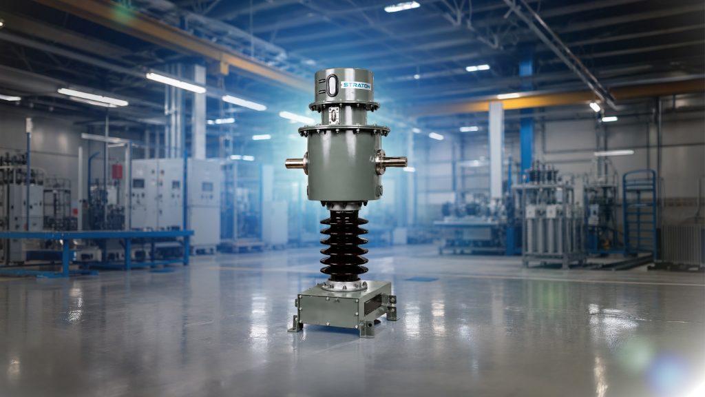
Protection class current transformer (CT) in an industrial electrical facility, used for fault protection and high-voltage power system applications.
Matching protection CT class to the right relay scheme is a recurring procurement gap — the table below maps common protection functions to the CT class they actually need.
| Relay / Protection Scheme | Typical Fault Current Behaviour | Recommended CT Class | Why |
| Overcurrent relay | Moderate fault multiples, single-ended sensing | 5P10 / 5P20 | Standard accuracy-limit class; no need for matched CTs since only one CT feeds the relay |
| Earth fault relay | Similar to overcurrent, often lower fault magnitude | 5P10 / 5P20 (sometimes 10P for less critical circuits) | Same accuracy-limit logic as overcurrent; class chosen against expected earth fault current |
| Differential relay (transformer/generator/motor) | Through-fault current typically 6–15× rated, per relay manufacturer guidance | 5P20 (modern microprocessor-based relays), PS/PX (older high-impedance schemes) | Modern biased differential relays tolerate standard P-class CTs; legacy high-impedance schemes still require matched knee-point CTs |
| Restricted Earth Fault (REF) | High-impedance scheme; requires matched CT behaviour on both sides of the zone | PS/PX class | REF depends on CTs saturating identically under external fault; a percentage-error class alone can’t guarantee this |
| Busbar protection | Fault current can exceed 20× rated, multiple CTs in one zone | PS/PX class | With many CTs summed in one scheme, mismatch risk is higher; knee-point specification is the safer standard practice |
Key procurement point: overcurrent relay and earth fault schemes can generally be served by standard P-class CTs sized to the actual fault level, but any scheme comparing multiple CTs against each other — REF, busbar, and (in older or high-impedance designs) a differential relay — needs PS/PX class CTs so all CTs in the zone saturate identically. Getting the protection ct class wrong at the relay scheme matching stage is one of the more expensive errors in a procurement specification to correct after manufacture. This distinction is standard practice in Indian utility tender specifications, including those issued by PGCIL and State Electricity Boards.
Straton Electricals manufactures across the full current transformer protection class spectrum — 5P and 10P general protection classes, and PS class for differential, REF, and busbar schemes — supplied to utilities, EPCs, and railway switchyards across India. Every unit is validated in-house at our 700 kV partial-discharge-free test lab and cross-checked at ERDA and CPRI, the same testing rigor covered in our earlier guide on partial discharge testing. Straton is ISO 9001:2015 certified and an approved vendor with RDSO, EIL, and MES.
As an Indian manufacturing base located in Hyderabad, Telangana, Straton is positioned to support utility and EPC orders with faster turnaround than typically available through import or outsourced testing routes — without compromising on IEC/IS-compliant protection CT classes.
One accuracy note before publishing: Straton’s own pages state slightly different delivery/warranty figures in different places; the product catalogue lists 2–3 week delivery, up to 3-year warranty, while one blog post separately mentions within one week, up to 5-year warranty.
|
Wound |
Eye Bolt |
Rigid/Bar |
A: 5P10 means the CT has a composite error of maximum 5% at its rated accuracy limit factor, which is 10 times the rated current. In simple terms, it tells you how accurately the CT performs when a fault current up to 10 times normal flows through it.
A: PS class (also called PX) is a special protection CT class used mainly for differential and restricted earth fault protection schemes. Instead of a fixed accuracy percentage, it’s defined by knee point voltage and other parameters, giving more precise control for balanced protection systems.
A: PS class (PX) CTs are typically preferred for transformer differential protection because these schemes need closely matched CT characteristics on both sides. Your relay manufacturer’s specification will usually confirm the exact knee point voltage and class required.
A: Generally no — a dual-core CT is used instead, with one core wound for metering accuracy and a separate core wound for protection accuracy. This is because the two applications need different behaviour at high fault currents, which a single core can’t optimally provide.
© Copyrights Straton Electricals Pvt. Ltd. 2025 . All rights reserved. Designed and Maintained By IRDM


