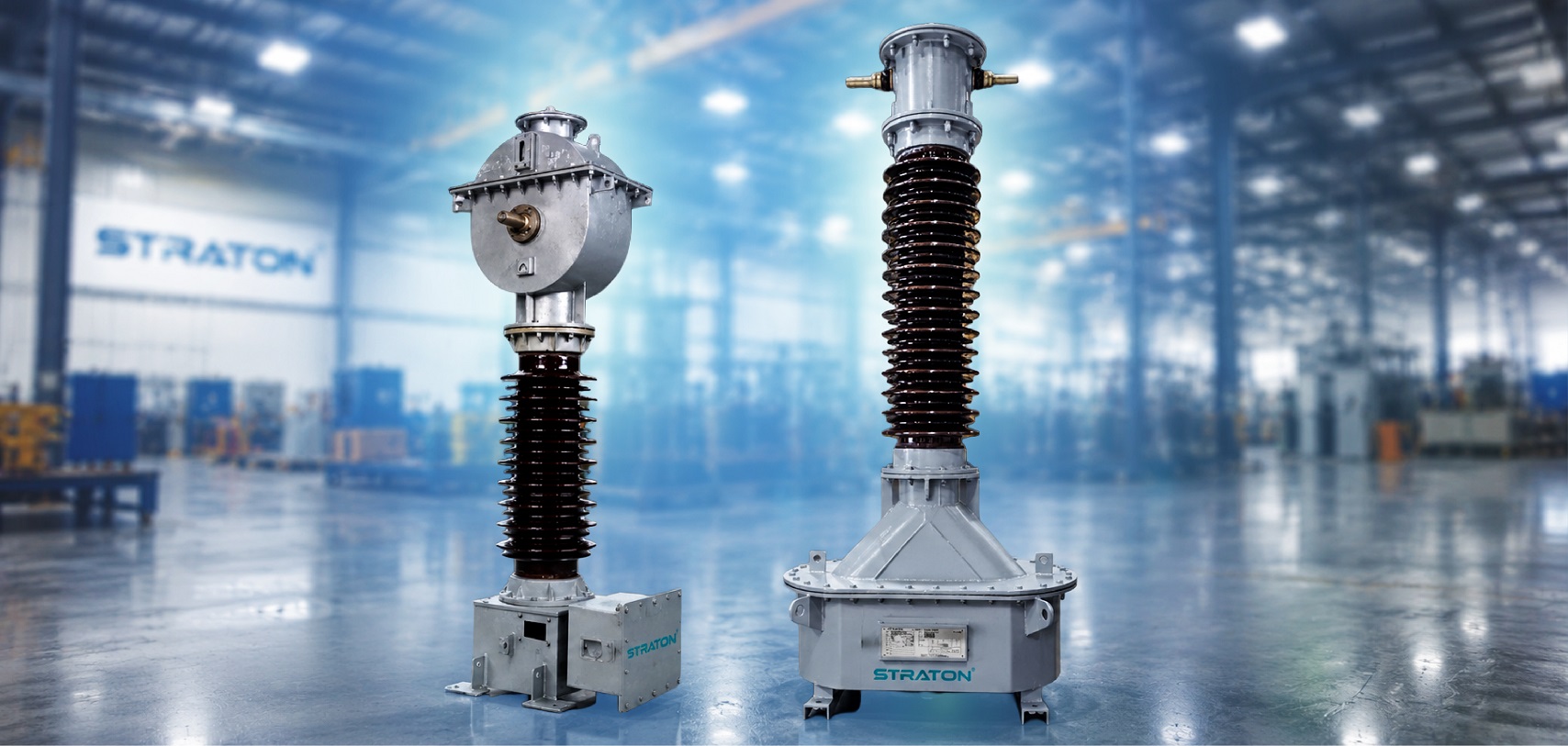
Partial discharge testing in instrument transformers is a non-destructive diagnostic method that detects localized insulation breakdown inside the transformer before it leads to full failure. It measures discharge magnitude in picocoulombs (pC), giving engineers an early warning sign of insulation weakness long before a visible fault develops making it a critical tool for ensuring long-term reliability in metering and protection circuits. Regular partial discharge test on transformer units helps catch this degradation while it’s still manageable, long before it turns into an outage.
In this guide, you’ll learn what partial discharge actually is, why it occurs inside instrument transformers, how the test is performed in practice, and which IS and IEC standards including IEC 60270 govern acceptable discharge limits. Understanding partial discharge testing in instrument transformers isn’t just a compliance checkbox, it’s one of the most reliable ways to catch insulation degradation before it becomes a costly failure in the field.
Why Is Partial Discharge Testing of Current Transformers Critical?
A partial discharge test of current transformer units matters because PD is an early sign of insulation degradation, visible long before an actual fault occurs. Left undetected, it progresses silently until failure.
PD originates in voids, cracks, or contamination, causing localized field concentration and repeated discharges, driving insulation aging through thermal and chemical damage. Void discharge behaviour varies by type: oil-filled insulation discharges at liquid-solid interfaces, while epoxy resin insulation discharges within cast voids. Undetected PD risks sudden in-service failure and safety hazards. Bodies like CPRI and ERDA support insulation testing standards in India, reinforcing PD testing as mandatory for critical installations.
What Causes Partial Discharge in Instrument Transformers — and How Design Prevents It
Most articles on partial discharge testing explain how to detect the problem. Far fewer explain where partial discharge comes from in the first place — yet for anyone specifying or buying a current transformer or voltage transformer, that is the more useful question. A partial discharge test of a current transformer does not create insulation quality; it only reveals it. The quality itself is decided years earlier, at the design and winding stage.
Partial discharge is a localised electrical breakdown that bridges only part of the insulation between two conductors. It does not cause immediate failure. It erodes the insulation gradually, and because insulation ageing follows a strongly non-linear relationship with electrical stress, even a modest increase in local field can shorten the service life of an instrument transformer disproportionately. This is why a low picocoulomb (pC) reading matters far beyond the test bay. That’s why a PD test of transformer units belongs at multiple stages of production, not just at the end — it catches design or winding flaws before they ever leave the factory.

The three root causes of partial discharge in instrument transformers
Insulation void and gas inclusions. A cavity trapped in paper, oil or cast resin has a lower permittivity than the surrounding solid insulation, so the electric field inside it is higher than in the material around it — while its breakdown strength is lower. The result is void discharge: the cavity breaks down repeatedly at a fraction of the applied voltage, eroding the surrounding insulation from the inside. In oil-impregnated paper (OIP) instrument transformers, voids are typically the residue of incomplete vacuum drying and oil impregnation. In cast-resin and dry-type units, they arise from imperfect casting or curing.
Moisture and contamination. Moisture in cellulose insulation lowers dielectric strength, raises dissipation factor (tan δ), and accelerates ageing. It also lowers the PD inception voltage — the threshold at which discharges begin. Rigorous vacuum drying, controlled impregnation, and a properly sealed enclosure are the only real defences.
Field concentration at edges and interfaces. The electric field does not distribute itself evenly. It concentrates at sharp edges, at the ends of conductive layers, and at boundaries between materials of differing permittivity. In a high voltage current transformer, the most critical of these regions is the condenser-graded bushing — and it is here that design, more than material, decides whether a unit is partial discharge free.
|
|
|
|
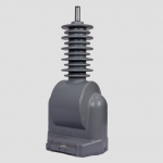
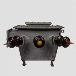
Why capacitance grading is the heart of a PD-free design
Inside a condenser-graded bushing, thin conductive foils are embedded at calculated intervals between the primary conductor and the earthed flange. These foils form a chain of series capacitors, and the voltage across each layer is inversely proportional to that layer’s capacitance. By sizing the foils correctly, the designer forces each layer to carry an approximately equal share of the total voltage.
That grading does two jobs at once:
- It distributes radial stress evenly through the insulation thickness, so no single layer is over-stressed.
- It grades the field axially along the length of the bushing, controlling the tangential stress that governs surface and creepage performance.
When the grading is well executed, the field is uniform and PD inception voltage sits comfortably above the operating and test voltages. When it is not — when foil geometry drifts, layers are unevenly sized, or foil edges are left sharp — the voltage distribution skews toward the weakest layers, local field rises, and partial discharge begins at test voltages the unit should comfortably withstand. A fine-graded bushing, with correctly proportioned layers and rounded, controlled foil edges, is therefore not a marketing phrase. It is the single most important reason a high voltage current transformer passes or fails its partial discharge test.
Design measures that suppress partial discharge
Manufacturers of instrument transformers use several complementary measures to keep discharge activity below the limits set by IEC 61869 and the relevant Indian standard:
- Fine capacitance grading of the bushing, with the foil geometry designed to equalise voltage per layer and eliminate local field concentrations.
- Controlled vacuum drying and oil impregnation, which removes moisture and eliminates the voids that seed void discharge in OIP insulation.
- A hermetically sealed enclosure with stainless-steel bellows to absorb thermal expansion of the oil without admitting air or moisture, keeping the insulation system dry across decades of thermal cycling.
- Rounded, burr-free conductor and foil edges, since every sharp edge is a field-concentration point and a potential PD source.
- Clean-room winding discipline and material traceability, because a single contaminant particle can become a discharge site.
What does this mean when you read a PD test report
A partial discharge test on an instrument transformer is, in effect, an audit of every one of the design and process decisions above. A unit that measures low, stable discharge at the specified test voltage is telling you that its insulation is void-free, dry, and correctly graded. A unit that shows rising discharge — or that passes only marginally is telling you something about how it was designed and built, not merely how it was tested.
This is why buyers of High Voltage Current Transformer and voltage transformers should look past the pass/fail line on the certificate and ask about the design behind it: how the bushing is graded, how the unit is dried and impregnated, how it is sealed, and whether every unit is routine-tested for partial discharge before dispatch — not only the type-test prototype.
When is the PD Test of Transformer Performed?
A PD test of transformer unit fits into distinct stages of the equipment lifecycle.
Type test proves the design meets the required standard, done once on a prototype — not on every unit. A special type test adds stricter conditions when a project’s spec demands it. Straton’s designs are type tested at national laboratories as standard practice.
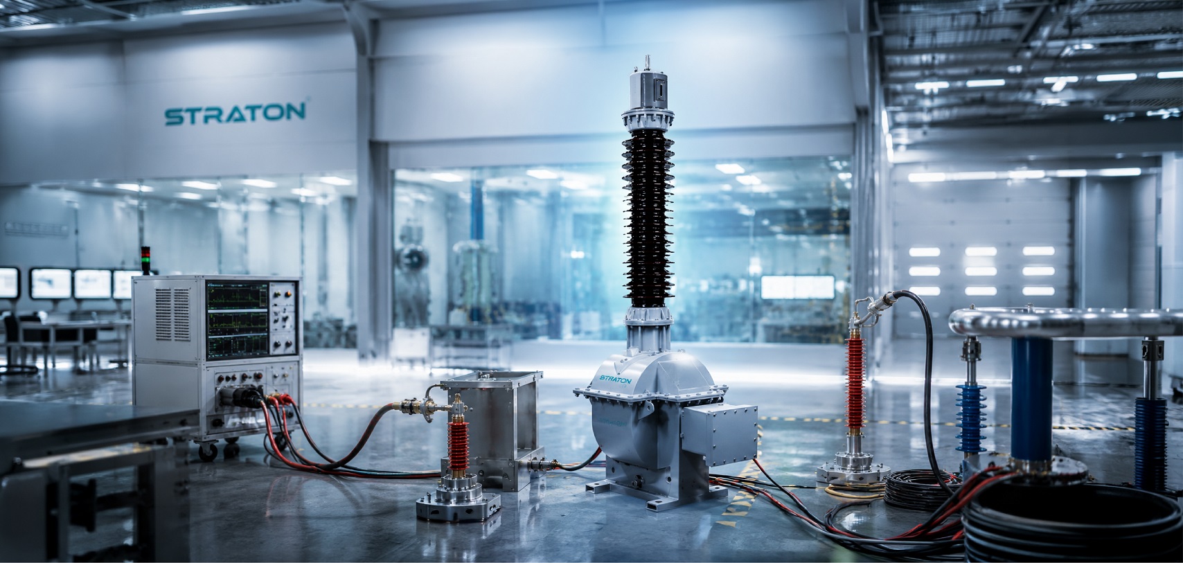
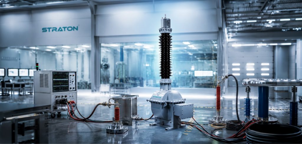
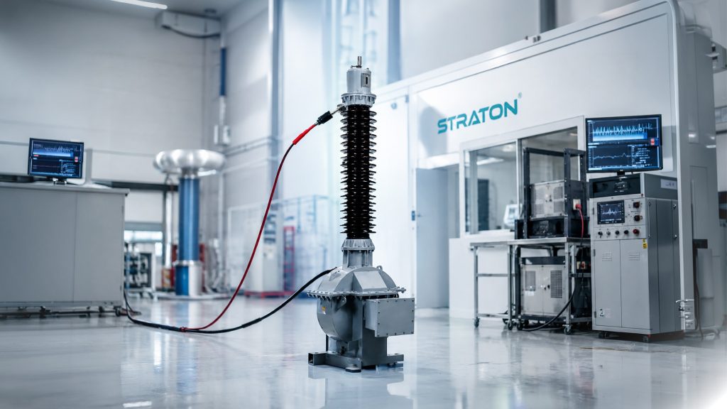
Routine test is performed on every manufactured unit before dispatch, since type testing validates the design but not each production unit. FAT confirms the specific equipment supplied for a project was built correctly. Straton’s 700kV Partial Discharge-free Series Resonance test lab, with a Static Frequency Converter for inductance and frequency regulation, supports this stage as part of their final testing sequence on every transformer.
Site Acceptance Testing is more common for larger power transformers; for instrument transformers it’s typically reserved for suspected transport/installation damage or when specifically required by project spec.
For Indian procurement — including PGCIL and State Electricity Board projects — which stage (type, routine, FAT, or site) is mandated is usually defined in the tender or technical specification, and should be confirmed before finalizing test scope.
How to Perform Partial Discharge Testing on Instrument Transformers
- Test method follows IEC 60270 principles, referenced within IEC 61869‑1 and IS 16227, using the bushing tap method as the standard circuit — the bushing’s capacitive tap connects to a measuring impedance, with the graded bushing itself acting as the coupling capacitor.
- Circuit is calibrated before every test: a charge injector feeds a known calibration pulse across the terminals so the detector’s scale factor matches this reference, de-energised, repeated at each terminal — calibration records are logged as part of the traceable test report.
- Test voltage is raised in stages above the rated voltage Un, held for a specified duration, then reduced to a lower enhancement level — the actual PD reading (in pC) is recorded at this lower voltage, not at peak.
- In practice, most flagged units show elevated discharge from incomplete oil impregnation, trapped air voids, or minor foil misalignment in the bushing — defects that surface at test but originate on the shop floor, which is why OEMs treat routine PD testing as a per-unit check, not a sample check
- Utilities and EPC contractors reviewing test reports typically expect calibration data, the applied test voltage sequence, and the measured pC value at each stage — documentation practices aligned with CPRI and ERDA testing conventions in India.
- Exact voltage levels and hold times vary by transformer type and rated voltage class; confirm against IEC 61869‑1, IS 16227, and the unit’s technical specification before publishing.
Permissible Partial Discharge Limits
Partial Discharge limits are set by IEC 61869‑1 and IS 16227, and vary by insulation type (oil-immersed vs. dry-type) and rated voltage class
Permissible discharge level is expressed in picocoulombs (pC), measured at the specified test voltage rather than at peak.
A unit passing at a stable, low pC reading indicates sound insulation; readings near the acceptance criteria warrant closer review of design and manufacturing quality.
Oil-Immersed vs Dry-Type CTs — Partial Discharge Test Behaviour Differences
| Aspect | Oil-Immersed CTs | Dry-Type (Cast Resin) CTs |
| Insulation type | Oil-impregnated paper (OIP) | Epoxy resin, cast via APG process |
| Primary PD cause | Residual moisture and voids from drying/impregnation | Gelation/casting defects (voids) |
| Moisture sensitivity | High — paper moisture reduced from typical 7–10% to under 0.5% during vacuum drying and impregnation | Low — hydrophobic, non-hygroscopic once cured and void-free |
| Humidity effect on insulation | Moisture-sensitive throughout service life; raises tan δ and lowers PD inception voltage | Comparatively stable across ambient humidity once properly cast |
| Applicable acceptance criteria | Separate permissible PD level under IS 16227 | Separate permissible PD level under IS 16227 |
| Test verification | Partial discharge test result checked against the oil-immersed limit, per BIS-aligned procedures | Partial discharge test result checked against the dry-type limit, per BIS-aligned procedures |
Key takeaway: the two insulation systems fail differently — one is moisture-driven, the other defect-driven — so a PD reading only means something when checked against the acceptance criteria for its own insulation type, not the other’s.
What Does a 700 kV Partial Discharge Testing Laboratory Mean for Quality Assurance?
Straton Electricals’ in-house 700 kV PD-free test lab reflects strong Indian manufacturing and testing capability, letting every unit undergo Partial Discharge Testing on-site, validated per BIS-aligned standards and cross-checked at ERDA and CPRI. Higher-voltage lab capacity enables testing of larger transformer ratings without third-party dependency — a common bottleneck for EPCs and utilities. This in-house capability is a trust signal, cutting turnaround time versus outsourced testing and supporting faster delivery.
|
|
|
|
FAQ
Q: Is Partial Discharge testing mandatory for a 33kV current transformer?
PD testing is generally required for 33kV and higher-rated CTs as part of type testing and often specified in utility tender documents. Requirements can vary by project and standard, so it’s best to confirm against your specific technical specification or IS/IEC requirement before finalising test scope.
Q: What is a good Partial Discharge value for a current transformer?
Lower picocoulomb (pC) readings generally indicate healthier insulation. Acceptable limits differ for oil-immersed versus dry-type CTs and are specified in the applicable standard. Your test report will confirm whether the reading falls within the permitted range for your transformer type.
Q: What’s the difference between routine and type Partial Discharge testing?
Type testing is done once to prove a design meets standards, usually on a prototype. Routine testing is done on every unit before dispatch to confirm consistent quality. Both use the same PD measurement principle but serve different purposes in the manufacturing process.
Q: Can Partial Discharge testing be done at site after installation?
Yes, though for instrument transformers, factory testing before dispatch is more common practice. Site testing is typically reserved for larger power transformers or when transport/installation damage needs to be ruled out.
Q: Why do oil-immersed and dry-type transformers have different Partial Discharge limits?
The insulation medium behaves differently under electrical stress — oil and dry resin have different discharge characteristics and failure modes. Standards account for this by setting separate permissible PD levels for each type, so results are judged against the right benchmark.