
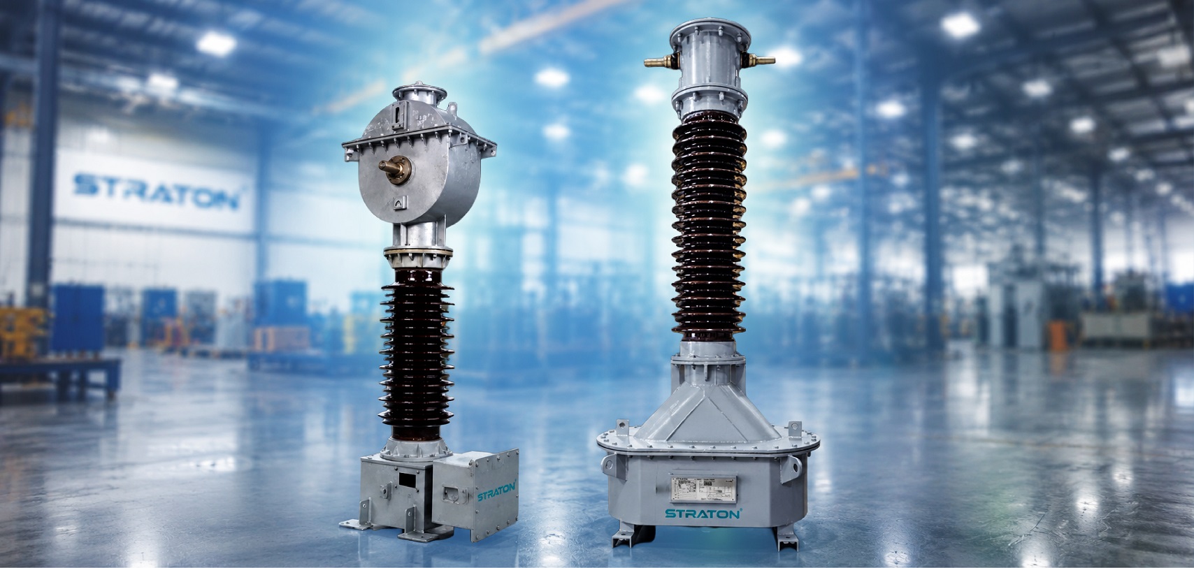
CT burden is the total load connected to the secondary winding of a current transformer (CT), expressed in VA (Volt-Amperes). It includes the resistance of measuring instruments, protection relays, connecting cables, and the CT secondary winding. Correct CT burden calculation ensures measurement accuracy, relay performance, and compliance with IEC standards.
Selecting a CT with the wrong burden rating can lead to inaccurate readings, relay maloperation, or premature CT saturation. Whether you’re designing a substation, industrial plant, or power distribution network, understanding CT burden is essential for reliable system performance.
In this guide, you’ll learn what CT burden means, how to calculate it using a simple formula, practical examples, common mistakes to avoid, and how to choose the right CT burden for electrical installations.
How Do You Perform Current Transformer Burden Calculation?
To perform a current transformer burden calculation, you need to evaluate the individual electrical loads imposed on the secondary circuit. Think of the burden current transformer setup as a source trying to push current through a loop. Everything in that loop resists the flow, creating a total current transformer burden.
CT Burden Formula
For featured snippet compliance and practical design engineering under IEC 61869 standards, the total ct burden is calculated using the following formula:
CT Burden (VA) = Secondary Current^2 x Total Circuit Resistance (Ohm)
Historically, engineers often attempted to add the load values directly in Volt-Amperes (VA). However, because these components are connected in series, the modern and technically precise method is to perform a burden ct calculation by executing a unit conversion where required—converting individual device burdens into burden resistance (Ohms), summing them up, and then finalizing the ct burden calculation.
Formally, the ct burden calculation formula is expressed as:
Total Burden (VA) = I^2 x R Total
Where each component in the formula represents:
- I (Secondary Current): The rated secondary current of the current transformer. In Indian power systems, this is standardly either 5A or 1A.
- R Total (Total Circuit Resistance / Burden Resistance): The combined sum of all resistances present in the secondary loop.
To complete a burden calculation for current transformer networks, you must sum every single component value in the secondary circuit using this formula:
R Total = R Cable + R Meter + R Relay + R CT Secondary
- Cable Resistance (R Cable): The total loop resistance of the copper or aluminum wires running from the CT terminal box to the panel. Because the current must travel out to the devices and return, you must always factor in the two-way distance (2 x one-way distance).
- Meter Burden (R Meter): The internal resistance of connected measuring instruments (like digital multi-function meters or ammeters).
- Relay Burden (R Relay): The internal resistance of the protection circuit devices (such as numerical overcurrent or earth fault relays).
- R CT Secondary: The internal winding resistance of the current transformer itself.
Important Unit Conversion Rule: Manufacturers typically state meter burden and relay burden in Volt-Amperes (VA) rather than Ohms. To accurately show the calculation using cable resistance, relay, and meter values together, you must convert these VA ratings into resistance using the standard formula: Resistance (Ohm) = VA / I^2.
Step-by-Step Calculation Example
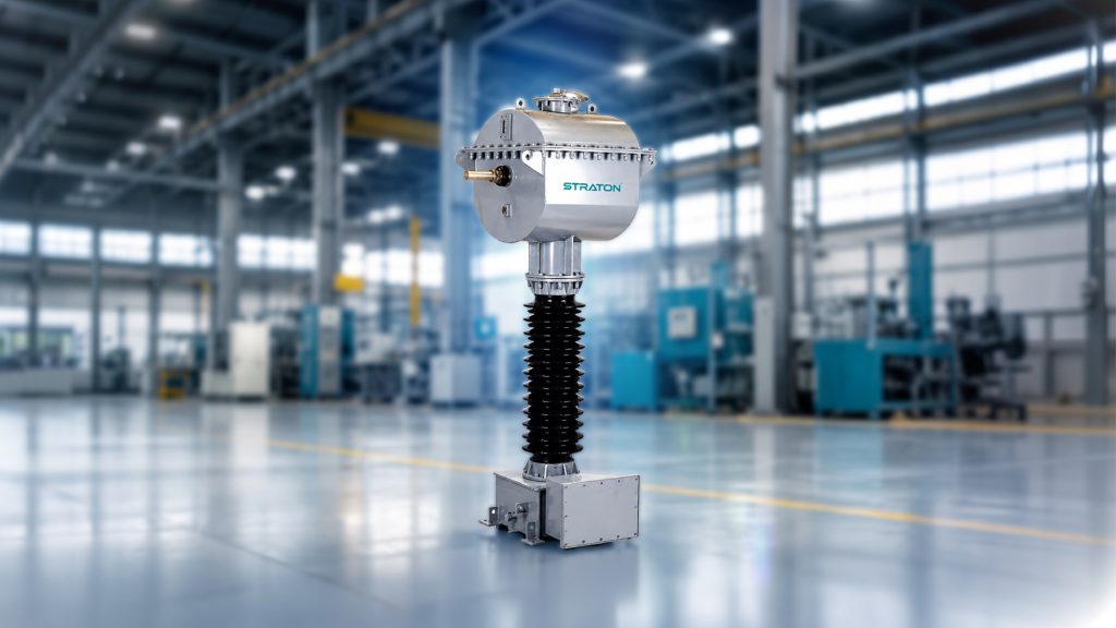
Let’s look at a practical calculation for an industrial substation application using a standard Straton 5A Current Transformer.
Given Design Data:
- CT Rated Secondary Current (I): 5A
- One-way distance from CT to Panel: 20 meters (Total loop length = 40 meters)
- Cable Type: Standard 2.5 mm^2 Copper Control Cable (Cable Resistance = 0.008 Ohm/meter at operating temperature)
- Meter Burden: 5 VA
- Relay Burden: 5 VA
Step 1: Calculate Total Cable Resistance
Using the loop distance, the total cable resistance is calculated as:
- R cable = 2 x 20 meters x 0.008 Ohm/meter = 32 Ohm
Step 2: Convert Instrument Burdens from VA to Ohms
Convert the equipment values from meter burden and relay burden from VA to Ohms based on the 5A secondary current layout (where I^2 = 25):
- Meter Resistance (R meter) = 0.5 VA / 5^2 = 0.5 / 25 = 02 Ohm
- Relay Resistance (R relay) = 1.5 VA / 5^2 = 1.5 / 25 = 06 Ohm
Step 3: Sum the Total Circuit Resistance
Combine the cable resistance, meter, and relay values to find the overall burden resistance:
- R total = R cable + R meter + R relay
- R total = 0.32 Ohm + 0.02 Ohm + 0.06 Ohm = 40 Ohm
Step 4: Calculate Final Calculated CT Burden (VA)
Apply the calculated circuit resistance back into the primary ct burden formula to get the total Volt-Amperes:
- Calculated Burden (VA) = I^2 x R total
- Calculated Burden (VA) = 5^2 x 0.40 Ohm = 25 x 0.40 = 10 VA
Result: The total circuit ct burden calculation yields exactly 10 VA. To guarantee that the current transformer maintains its accuracy class and operates safely without saturation risks, a standard Straton current transformer rated for 10 VA or 15 VA should be selected for this setup.
|
|
|
|

What Components Contribute to the Burden of a Current Transformer?
The burden on a current transformer isn’t a single value — it’s the combined effect of every component connected in the secondary circuit. Understanding each contributor separately makes it much easier to diagnose accuracy issues or select the right CT for a given metering circuit.
The main components that make up total burden impedance are protective relay burden, energy meter burden, cable impedance, and the CT’s own secondary winding resistance.
Relay Burden
Protective relays are among the most common contributors to burden current transformer calculations, particularly in protection-class applications. A protective relay draws a defined VA load from the CT secondary circuit in order to operate its measurement and tripping logic.
Relay burden depends heavily on the relay type:
- Electromechanical relays typically draw a higher burden, since they rely on physical coils and moving parts to operate
- Numerical or microprocessor-based relays (common in modern overcurrent and earth fault protection) draw significantly less burden, often a fraction of a VA
Relay burden values are always listed in the manufacturer’s datasheet, and should be converted to burden resistance using R = VA ÷ I² before being added to total circuit resistance.
Cable Burden
Cable burden — sometimes called secondary lead resistance — is one of the most overlooked contributors to total burden, especially in larger installations where the CT sits some distance from the panel.
Cable burden depends on three factors:
- Length of the run — total loop length is always twice the one-way distance
- Cross-sectional area of the conductor — thinner cables carry higher resistance per meter
- Conductor material — copper offers lower resistance than aluminum for the same cross-section
In substations or industrial installations with long cable runs, cable impedance can easily become the largest single contributor to total circuit resistance.
Meter Burden
Energy meters and other measuring instruments also draw a defined burden from the CT secondary circuit. Compared to relays, meter burden is generally the smallest contributor to total burden — lower still for modern digital and electronic meters compared to older analog designs.
Comparison Table: Burden Contributors
| Component | Unit | Typical Contribution |
| Relay | VA | Medium |
| Meter | VA | Low |
| Cable | Ω / VA | Medium to High |
| CT Secondary Winding | Ω | Fixed |
Why Modern Relays and Meters Have Changed CT Burden Calculation
Most guidance on current transformer burden calculation was written for a generation of equipment that no longer exists. Understanding what changed is the difference between a correctly specified CT and one that is over-specified, over-priced, or quietly out of accuracy class.
Then: the burden lived in the devices. Electromechanical relays and induction-disc energy meters drew significant power from the CT secondary — commonly 1 to 3 VA each, and sometimes more. With several such devices in a metering or protection circuit, the connected devices dominated the total burden, and cable resistance was almost a rounding error. A 30 VA CT was a reasonable specification.
Now: the burden lives in the cable. Modern numerical relays and digital energy meters draw very little — typically in the region of 0.1 to 0.5 VA each. The instrument burden has collapsed by an order of magnitude. What has not changed is the copper between the CT and the panel. In a modern substation, secondary lead resistance is usually the dominant contributor to total CT burden — often the majority of it.
This has three practical consequences for anyone performing a burden calculation for a current transformer:
- Legacy specifications routinely over-specify burden. A 30 VA rating carried forward from an older standard tender may be several times what the circuit actually requires. Over-specifying burden means a physically larger, costlier CT with more core material — and, as the next section explains, it can degrade protection performance rather than improve it.
- Cable burden deserves the most attention in your calculation, not the least. It is the term most often estimated carelessly and most often wrong.
- The choice between a 1A and 5A secondary now matters more, not less. Because burden rises with the square of secondary current, the same cable run imposes 25 times the burden on a 5A CT that it does on a 1A CT. Where cable runs are long — as in most transmission substations — a 1A secondary is frequently the correct engineering answer.
Typical Burden Contributions — Modern vs Legacy Equipment
| Burden contributor | Legacy equipment | Modern equipment |
| Protection relay | ~1–3 VA (electromechanical) | ~0.1–0.5 VA (numerical) |
| Energy meter | ~1–3 VA (induction disc) | ~0.1–0.5 VA (digital/static) |
| Secondary cable (leads) | Often minor | Frequently dominant |
| CT secondary winding | Fixed, small | Fixed, small |
Figures above are typical ranges for guidance only. Always use the actual VA burden stated on the relay, meter and cable datasheets for your project.
The Cable Burden Mistake Almost Everyone Makes
Cable resistance must be calculated on the round-trip (loop) length of the conductor — the run out to the device and the return path — not the one-way distance. A 40-metre panel run is 80 metres of copper in the burden calculation.
This single error understates cable burden by half, and it is the most common reason a CT burden calculation that looks correct on paper fails in the field. Where the return path is shared or the wiring is not a simple two-wire run, trace the actual circuit before assuming.
CT Burden Formula: Calculation Example for Industrial Installations
The ct burden formula matters most in installations like substation CT setups and industrial switchgear, where cable runs and connected devices determine actual burden versus rated burden. This example shows current transformer sizing for a typical protection system, relevant to large installations such as those used by NTPC.
Example: 5A Protection CT
Consider a 5A CT in a protection scheme for an industrial substation panel.
Given Data:
- Secondary Current (I): 5A CT (same method applies for a 1A CT, substituting I = 1)
- One-way cable distance: 30 meters (loop length = 60 meters)
- Cable: 2.5 mm² copper, resistance ≈ 0.008 Ω/meter
- Relay Burden: 0.3 VA (modern numerical relay)
- Meter Burden: 0.2 VA (modern digital meter)
Step 1: Cable Resistance
R cable = 2 × 30 × 0.008 = 0.48 Ω
Step 2: Convert VA to Resistance (I² = 25)
Relay = 0.3 / 25 = 0.012 Ω
Meter = 0.2 / 25 = 0.008 Ω
Step 3: Total Resistance
R total = 0.48 + 0.012 + 0.008 = 0.50 Ω
Step 4: Total VA Burden
Burden = I² × R total = 25 × 0.50 = 12.5 VA
How to Verify Against Rated Burden
Calculated burden is 12.5 VA. A 15 VA rated 5A CT covers this with reasonable margin. As the numbers show, cable resistance (0.48 Ω) dominates the total far more than relay and meter burden combined (0.02 Ω) — consistent with modern low-burden digital equipment, where cable burden is now the main factor to calculate carefully in current transformer sizing for substation CT and industrial switchgear protection systems.
Can CT Burden Be Too Low? Understanding Under-Burdening
Almost every guide warns about exceeding the rated burden of a current transformer. Very few mention the opposite problem — and with today’s low-burden digital equipment, it has become the more likely one.
A CT’s accuracy class is guaranteed over a burden range, not up to a maximum. Under IEC 61869-2, the accuracy of a metering CT is verified between a lower and an upper limit of its rated burden — conventionally from 25% to 100% of the rated burden, at the rated power factor. A CT operating below that lower limit is outside the conditions under which its accuracy class was proven.
This is not a theoretical concern. Consider a 15 VA metering CT specified years ago for an electromechanical meter, now connected to a modern digital meter drawing 0.2 VA over a short cable run. The connected burden may be well under 25% of rated. The CT is not damaged, and it will produce a reading — but that reading is no longer covered by the accuracy class stated on the nameplate. For revenue metering, where a 0.2S class CT was specified precisely to guarantee billing accuracy, this quietly defeats the purpose of the specification.
What This Means for CT Specification
The practical rule that follows is simple, and it inverts the usual advice:
Specify the CT burden to match the circuit you are actually building — not the largest burden you can imagine. A CT should be selected so the connected burden falls comfortably within the guaranteed range: high enough to clear the lower limit, with margin below the rated value for future additions.
In practice this means:
- Calculate the real total burden (relay + meter + cable loop + terminal blocks) using actual datasheet figures.
- Select the nearest standard rated burden above it — for most modern circuits this is 5 VA or 10 VA, not 30 VA.
- Where a low-burden digital circuit is unavoidable, discuss it with the CT manufacturer. A CT can be designed for a lower rated burden so that the connected load sits within the guaranteed accuracy range.
- Do not simply carry forward a legacy burden figure from an old tender document without recalculating it.
This is a design conversation worth having before the CT is manufactured. It is difficult to correct afterwards.
|
|
|
|
Common CT Burden Mistakes and Best Practices
Getting CT burden wrong is common. It affects CT accuracy. It can cause CT saturation. It also hurts protection relay performance.
Mistakes That Reduce CT Accuracy
- Ignoring cable burden is a frequent mistake. Cable resistance adds up over long runs. Skipping it gives wrong results.
- Using one-way length instead of loop length is another error. This understates the burden by half.
- Choosing an incorrect CT burden rating causes problems too. Oversizing wastes cost. Undersizing leaves no safety margin.
- Overlooking secondary current rating matters. A 5A instrument transformer creates more burden than a 1A unit for the same cable. Long cable runs favor 1A secondaries.
- Ignoring accuracy class limits reduces performance. IEC 61869-2 guarantees accuracy only between 25% and 100% of rated burden. Going above or below this range lowers accuracy.
Best Practices for Engineers
- Calculate total burden using real datasheet values. Include winding resistance, cable resistance, and device resistance.
- Always use loop cable length, not one-way length.
- Match rated burden closely to actual burden. Keep a safety margin, but avoid oversizing.
- Prefer a 1A secondary for long cable runs. This reduces losses and burden.
- Use good-quality, low-resistance cables. Keep cable runs short where possible.
- Follow IEC 61869-2 Check standards from CPRI, ERDA, and BIS Standards.
- Discuss unusual burden needs with the CT manufacturer early. This avoids costly rework later.
How CT Burden Affects Protection Performance — ALF and Knee-Point Voltage
For metering CTs, burden governs accuracy. For protection CTs, burden governs something more consequential: whether the CT can faithfully reproduce a fault current long enough for the relay to operate. Getting this wrong does not produce a slightly inaccurate bill — it produces a relay that fails to trip.
Burden and the Accuracy Limit Factor (ALF)
A protection CT is specified with an Accuracy Limit Factor — the multiple of rated primary current up to which the CT will reproduce current within its stated composite error. A 5P20 CT, for example, maintains within 5% composite error up to 20 times rated primary current.
The essential point is that the ALF is defined at the CT’s rated burden, and the effective ALF changes with the actual connected burden:
- Connected burden below rated burden → effective ALF increases. The CT saturates later than its nameplate suggests, and the protection has more margin.
- Connected burden at or above rated burden → effective ALF falls. The CT saturates earlier than the nameplate implies.
This is why an over-burdened protection CT is dangerous: under a heavy through-fault, it saturates, the secondary current collapses, and the relay may under-reach, mis-operate, or fail to trip at all. It is also why the over-specification habit described earlier is not harmless — a CT with an unnecessarily high rated burden that is then lightly loaded behaves differently from what the specification intended, in both directions.
Burden and Knee-Point Voltage (PX / PS Class CTs)
For class PX (or PS) CTs — used in high-impedance busbar protection, restricted earth fault, and differential schemes — burden enters the calculation directly through the knee-point voltage requirement.
The knee-point voltage the CT must deliver is driven by the fault current the scheme must accommodate, multiplied by the total secondary circuit impedance: the CT secondary winding resistance plus the loop resistance of the leads plus the relay burden. The scheme designer specifies a minimum required knee-point voltage on that basis.
The consequence is direct and often underestimated: longer cable runs raise the required knee-point voltage, which drives a physically larger CT core. On a long-lead installation, lead resistance can dominate the requirement. This — again — is why a 1A secondary is so often preferred in transmission substations: it reduces the burden imposed by long leads by a factor of 25 compared with a 5A secondary, and with it the required knee-point voltage and the size and cost of the CT.
The Design Checklist for Protection CTs
- Calculate the total secondary circuit impedance, including CT winding resistance and the loop lead resistance.
- Confirm the effective ALF at the actual connected burden — not merely the nameplate ALF at rated burden.
- For PX/PS class CTs, verify the required knee-point voltage against the scheme’s fault-current and impedance requirements.
- Consider a 1A secondary wherever cable runs are long.
- Share the full circuit data — lead length, conductor cross-section, relay model and burden, and the protection scheme — with your CT manufacturer at the enquiry stage. Correct burden specification is far cheaper than a re-manufactured core.
Current Transformer Burden Selection Guide for Utilities and Industrial Projects
Selecting the right current transformer burden rating means matching the CT to actual circuit demand — not defaulting to the highest available rating. Across Indian utility and industrial projects, typical burden ratings in use are 5 VA, 10 VA, 15 VA, and 30 VA, though modern digital equipment often needs far less. Straton’s own range reflects this: low voltage CTs run 1.0–20 VA, while Medium Voltage Current Transformers (1.2kV–36kV) in combined CTPT units carry standard 5 VA and 10 VA ratings, with higher burdens available on request for larger installations. Choice depends on protection CT vs metering CT application, cable length, and connected load.
Recommended Burden Ratings
- 5 VA: Suited to short cable runs with modern digital meters and numerical relays, where combined device burden is low
- 10 VA: A common general-purpose rating for standard metering CT installations, including Straton’s MV CTPT range, covering moderate cable lengths
- 15 VA: Used where cable runs are longer or multiple devices share the same CT secondary circuit
- 30 VA: Typically reserved for legacy installations or electromechanical relays; for most modern circuits, Straton’s standard ratings up to 20 VA (or higher on request) are usually sufficient
Select a rated burden close to 125% of the actual calculated burden — enough margin without pushing the CT outside its accuracy class.
Selection Checklist
- Calculate actual circuit burden (relay + meter + cable resistance) before selecting a rating
- Confirm protection CT vs metering CT requirements, since accuracy class needs differ
- Apply the ~125% rule rather than defaulting to the largest available option
- Account for cable length and secondary current (1A vs 5A) at the design stage, not after installation.
- For EPC projects, coordinate burden specifications with the project electrical consultant at the tendering stage to ensure CT ratings align with final connected load requirements
- For burden needs above standard catalogue ratings, request custom specification directly
- Cross-check specification against applicable standards and guidance from bodies such as CEA and State Electricity Boards, particularly for PGCIL-linked or utility-scale projects
- Involve electrical consultants early for non-standard accuracy or fault-current requirements
- Testing and commissioning for Indian utility and industrial projects typically follow type-test and routine-test protocols aligned with IEC 61869, with site acceptance often requiring burden verification at the actual connected load rather than relying solely on nameplate ratings
FAQ
Q: What happens if the CT burden exceeds the rated value?
When the actual burden is higher than the CT’s rated burden, measurement accuracy decreases and the CT may saturate during fault conditions. This can affect energy meters and protection relays, leading to incorrect readings or delayed tripping. Proper burden calculation helps avoid these issues.
Q: Is 1A CT better than 5A CT for long cable runs in India?
Yes. A 1A CT generally produces lower cable losses because the burden depends on the square of the secondary current. For substations with long cable runs, many consultants prefer 1A CTs to reduce burden and improve overall measurement accuracy, especially in utility and industrial applications.
Here are concise, SEO-friendly answers suitable for an FAQ section or featured snippets.
Q: What is the burden rating of a CT?
The burden rating of a current transformer (CT) is the maximum load that can be connected to its secondary winding while maintaining its specified accuracy. It is expressed in VA (volt-amperes) at a specified power factor, such as 5 VA, 10 VA, 15 VA, or 30 VA. The total burden includes the connected meters, relays, and secondary wiring.
Q: What is the secondary burden of a CT?
The secondary burden of a CT is the total electrical load connected to the CT’s secondary circuit. It includes the burden of measuring instruments, protection relays, terminal blocks, and connecting cables. If the connected burden exceeds the CT’s rated burden, measurement accuracy may decrease, and protection performance can be affected.
Q: What accuracy classes are available for metering CTs?
Cover 0.1/0.2/0.2S/0.5/0.5S/1 under IEC 61869-2, explaining that 0.2S (the “S” = special, accurate down to 1% of rated current)
Conclusion
Correct CT burden calculation is essential for maintaining current transformer accuracy, reliable relay operation and long-term system safety. By understanding the burden formula, considering cable resistance and selecting the correct rated burden, engineers can avoid costly design errors.
Need help selecting the right CT burden for your project? Contact Straton Electricals for expert guidance on metering and protection current transformers, including High Voltage Current Transformers, customised engineering support, and a free technical consultation for your utility, EPC or industrial application.



1 Comment